4 6 8 12 24 48 Core GYTC8S Figure 8 Self Supporting Fiber Optic Cable
Description
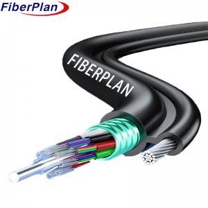
In the construction of this cable, the fibers are arranged within a loose tube crafted from high modulus plastic.
To enhance water resistance, the tubes are filled with a specialized water-resistant compound. Acting as a c-
entral strength member, a steel wire is positioned within the core. The tubes, along with fillers, are stranded
around the strength member to form a compact and circular cable core. Following this, a Polyethylene (PE)
sheath is applied around the cable core, along with stranded wires serving as support. The final result is a figure
8 structure, making this cable particularly suitable for self-supporting aerial installations.
Application
1 Suitable for Aerial and Pipeline Laying Method: Designed to be used effectively in both aerial and pipeline
installation methods, offering versatility in deployment.
2 Adopted for Outdoor Distribution: Tailored for outdoor distribution scenarios, ensuring resilience and perfo-
rmance in varied environmental conditions.
3 Ideal for Long-Distance and Local Area Network Communication: Well-suited for both long-distance and local
area network communication, providing reliable connectivity for diverse communication needs.
Characteristics
* Good Mechanical and Temperature Performance: Demonstrates reliable mechanical strength and temp-
erature resistance, ensuring durability in various conditions.
* High Strength Loose Tube with Hydrolysis Resistance: The cable incorporates a high-strength loose tube
designed to resist hydrolysis, enhancing its longevity and performance.
* Special Tube Filling Compound for Fiber Protection: Utilizes a specialized tube filling compound to provide
critical protection to the fibers, enhancing their overall safety and performance.
* Crush Resistance and Flexibility: Exhibits crush resistance while maintaining flexibility, allowing for versatility
in installation and protection against external pressures.
* PE Sheath for UV Radiation Protection: The Polyethylene (PE) sheath serves as a protective layer, shielding
the cable from the harmful effects of ultraviolet (UV) radiation.
Cable construction details
| No. of fibers | 6 | 12 | 24 | 48 | 72 | 96 | 144 |
| No. of tubes | 1 | 1 | 2 | 4 | 6 | 8 | 12 |
| fibers per tube | 6 | 6 | 6 | 12 | 12 | 12 | 12 |
| Filler Rod | 4 | 3 | 1 | 1 | 0 | 0 | 0 |
| Tube diameter (±0.1mm) | 2.0 | 2.0 | 2.0 | 2.0 | 2.0 | 2.0 | 2.0 |
Thickness of loose tube
(±0.05mm) | 0.3 | 0.3 | 0.3 | 0.3 | 0.3 | 0.3 | 0.3 |
| Outer diameter (±0.5mm) | 5.4X8.6
-15.0 | 5.4X8.6
-15.0 | 5.4X8.6
-15.0 | 5.4X9.8
-16.5 | 5.4X10.8
-17.5 | 5.4X12.2
-19.0 | 5.4X14.9
-22.0 |
Thickness of out diameter
(±0.1mm) | 1.6 | 1.6 | 1.6 | 1.6 | 1.6 | 1.7 | 1.7 |
| Loose tube | Material | PBT | Color | Standard spectrum |
| Water blocking system | Material | Water blocking tape / Filling gel |
| Armor | Material | Corrugated steel tape |
| Central strength member | Material | Steel wire | Size | 1.4mm(6-48)
2.0mm(72-144) |
| Mental strength member | Material | Stranded steel wire | Size | 1.0mm*7 |
| Gallus | Material | PE | size
(h*w) | 2.0*1.5mm |
| Outsheath | Material | PE | Color | Black |
Cable mechanical and environment chararcteristics
| Tensile strength | Long term(N) | 3000N |
| Short term(N) | 7000N |
| Crush load | Long term(N) | 300N/100mm |
| Short term(N) | 1000N/100mm |
| Bending radius | Dynamic | 20D |
| Static | 10D |
| Installation Temperature | -10℃~+60℃ |
| Storage Temperature | -40℃~+70℃ |
Fiber characteristics
| Fiber type | Unit | SM G652D | MM 50/125 | MM 62.5/125 |
| Condition | mm | 1310/1550 | 850/1300 | 850/1300 |
| Attenuation | dB/km | ≤0.36/0.24 | ≤3.0/1.5 | ≤3.0/1.5 |
| Cladding diameter | um | 125±0.8 | 125±0.8 | 125±0.8 |
| Cladding non-circularity | % | ≤1.0 | ≤1.0 | ≤1.0 |
| Coating diameter | um | 242±6 | 242±6 | 242±6 |