Outdoor ADSS Cable for Aerial Fiber Optic Networks with Enhanced Tensile Strength
Description
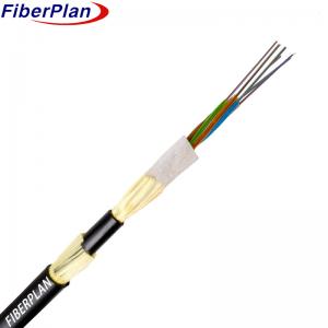
The ADSS (All-Dielectric Self-Supporting) cable utilizes a robust construction methodology. The fibers are
encased within high modulus plastic tubes, safeguarded further by a water-resistant compound. These tu-
bes, along with their fillers, envelop a Fiber Reinforced Plastic (FRP) core, fortifying the cable's structural
integrity into a compact circular arrangement. Once filled with additional compound for added protection, a
thin Polyethylene (PE) inner sheath is applied to shield the cable core. Strengthening the assembly, a layer
of aramid yarns is stranded over the inner sheath, enhancing tensile strength. The cable is finalized with an
outer sheath, choosing between PE or Anti-Tracking (AT) material, offering comprehensive defense against
environmental factors, ensuring durability and reliability in telecommunications networks.
Application
1 Voltage Specification: The design of ADSS cables accounts for the voltage levels of overhead power lines.
For lines operating under 110kV, a Polyethylene (PE) outer sheath is chosen. This material offers suitable
protection and insulation for lower voltage environments.
2 High Voltage Compatibility: In cases where power lines are rated at or above 110kV, an Anti-Tracking (AT)
outer sheath is applied in the ADSS cable design. The AT material is specifically chosen for its ability to provide
enhanced insulation and withstand higher voltage environments effectively.
3 Aramid Design Customization: The quantity and stranding process of aramid yarns within the ADSS cable are
purposefully designed and tailored to accommodate different spans between poles or supports along the power
lines. This customization ensures the cable's strength and resilience across various distances, meeting specific
installation requirements.
4 Performance Optimization: By considering the voltage, environmental factors, and installation conditions, the
ADSS cable design optimizes performance and durability. This meticulous approach ensures that the cable
meets the demands and challenges posed by different voltage levels and installation scenarios along overhead
power lines.
Characteristics
1 Exceptional Mechanical and Temperature Performance: ADSS cables excel in both mechanical resilience
and temperature resistance, ensuring reliability in harsh conditions.
2 Hydrolysis-Resistant, High-Strength Loose Tube: The cable's loose tube, resistant to hydrolysis, maintains
high strength, protecting the enclosed fibers from moisture-related damage.
3 Specialized Tube Filling Compound: The use of a specialized filling compound within the tubes provides
crucial protection to the fibers against environmental factors, enhancing their longevity and performance.
4 Crush Resistance and Flexibility: Balancing crush resistance with flexibility ensures the cable can withstand
pressure without compromising its ability to bend and adapt to installation needs.
5 Tensile Strength Supported by Dual Parallel Steel Wires: Dual parallel steel wires enhance the cable's tensile
strength, providing robust support and stability.
6 Compact Size, Lightweight Build, and Easy Installation: These cables are designed to be compact, lightweight,
and easy to install, offering convenience to users during deployment.
Cable construction details
| Number of fiber | 24-144 core |
| Filling rope | 2-0 |
| Moisture Barrier | Water blocking system |
| Central strength member | material | FRP/FRP with PE |
| size | 2.1mm |
| Tube-filling | Tube filling compoun |
| filler | PP tube/ PVC tube |
| Inner sheath | material | PE |
| Loose tube | material | PBT |
| diameter | Ф2.2(outer/inner) |
| Outer sheath | material | PE/HDPE |
| diameter | 1.7±0.2mm |
Fiber color
| Number of fiber 8 cores per tube | 1 | 2 | 3 | 4 | 5 | 6 |
| Blue | Orange | Green | Brown | Grey | White |
| 7 | 8 | 9 | 10 | 11 | 12 |
| Red | Black | Yellow | Violet | Pink | Aqua |
| Color 13~24 will be marked with a black tracer. For black color no need marked black tracer, will use nature color instead. |
Cable Mechanical characteristic
| core | Cable diameter | Weight |
| 2 core to 60core | 12±0.3mm | 140±3kg/km |
| 72core | 13±0.3mm | 190±3kg/km |
| 96core | 14.5±0.3mm | 220±3kg/km |
| 144core | 16.5±0.3mm | 240±5kg/km |
| Rec.daily max working tension | 88kN |
| Max. Allowable working tension | 32.7KN |
| Modulus of elasticity | 37KN/mm2 |
| Min Bending Radius(mm) | Operation | 240mm |
| Installation | 390mm |
| Extra load | Extra load 0.5% ~ 0.7% |
| Ice | 5mm |
| Wind speed | 35m/s |
Fiber characteristic
| Fiber style | Unit | SM
G652 | SM
G652D | MM
50/125 | MM
62.5/125 | MM
OM3-300 |
| condition | nm | 1310/1550 | 1310/1550 | 850/1300 | 850/1300 | 850/1300 |
| attenuation | dB/km | ≤ | ≤ | ≤ | ≤3.0/1.0 | ≤3.0/1.0 |
| 0.36/0.23 | 0.34/0.22 | 3.0/1.0 | ---- | ---- |
| Dispresion | 1550nm | Ps/(nm*km) | ---- | ≤18 | ---- | ---- | Dispresion |
| 1625nm | Ps/(nm*km) | ---- | ≤22 | ---- | ---- | |
| Bandwith | 850nm | MHZ.KM | ---- | ---- | ≧400 | ≧160 | Bandwith |
| 1300nm | MHZ.KM | ---- | ---- | ≧800 | ≧500 | |
| Zero dispersion wavelength | nm | 1300-1324 | ≧1302,
≤1322 | ---- | ---- | ≧ 1295,
≤1320 |
| Zero dispresion slope | nm | ≤0.092 | ≤0.091 | ---- | ---- | ---- |
| PMD Maximum Individual Fibr | | ≤0.2 | ≤0.2 | ---- | ---- | ≤0.11 |
| PMD Design Link Value | Ps(nm2*k
m) | ≤0.12 | ≤0.08 | ---- | ---- | ---- |
| Fibre cutoff wavelength λc | nm | ≧ 1180,
≤1330 | ≧1180,
≤1330 | ---- | ---- | ---- |
Cable sutoff
wavelength λcc | nm | ≤1260 | ≤1260 | ---- | ---- | ---- |
| MFD | 1310nm | um | 9.2+/-0.4 | 9.2+/-0.4 | ---- | ---- | ---- |
| 1550nm | um | 10.4+/-0.8 | 10.4+/-0.8 | ---- | ---- | ---- |
Numerical
Aperture(NA) | | ---- | ---- | 0.200±0.015 | 0.275±0.
015 | 0.200±0
.015 |
Step(mean of bidirectional
measurement) | dB | ≤0.05 | ≤0.05 | ≤0.10 | ≤0.10 | ≤0.10 |
Irregularities over fiber
length and point | dB | ≤0.05 | ≤0.05 | ≤0.10 | ≤0.10 | ≤0.10 |